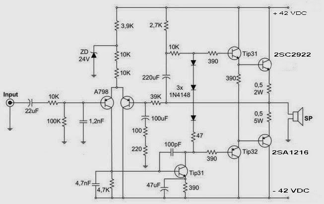
Skema Rangkaian Driver Power Amplifier
It is perfectly ok to have “non 5Vs” coming out of a 5V regulator. All your voltages should be referenced to a common point. Having it as you show it, even if you are copping others, IS confusing.
The regulator is just a component, not the final design. By the argument you put forward, any variable power supply that uses, for example, a LM317 regulator would have a 1.25V output all the time as it is a 1.25V voltage regulator. The LM317 is just a part of a circuit that happens to be a 1.25V regulator, but produces a variable output. The same way the regulators in this circuit are being used to produce “non 5V” power rails. They are just used to get a power rail that is offset by 5V from another rail. But all rails are measured W.R.T.
Skema Pemasangan Transistor Final Power - Duration: 5:11. How to add more transistor to amplifier.
I wouldn’t go lower than 20-24V for the power supply,but at least 30V is recommended. For low power amplifier, I think a different design would be better. Nothing to hide game.
If you are using a transformer (I recommend toroidal because of their size), and not a SMPS, you will need a bridge rectifier and some beefy filtering caps (I personally used 2x10 000uF per branch - positive/negative). About the potentiometer, although you could add one before the ” Input -P1” of value 100K, I suggest building a pre-amp circuit that also has tone control. It is +12V referenced to -30V. Imagine that we use a multimeter and we put the black probe (ground) to the -30V rail. If we measure the real ground (which is 0V), on the multimeter digit we would read +30V.
Tfile ru bistrij torrent full. Our service has detected that Russian is used on the page, and it matches the claimed language. Language claimed in HTML meta tag should match the language actually used on the web page. Otherwise New-tfile.org can be misinterpreted by Google and other search engines.
If me measure “+12V”, on the multimeter it reads +12V. BUT, if we put the black probe on the 0V ground, on the multimeter we would have -18V. We measure the electric potential difference, V2-V1. When we measure “+12V” rail, we consider “-30V” supply to be V1. I used this notation because we connect the COM and VSS port of the IR2110 to the “-30V” rail. If you want to build an amplifier with such a low output this schematic will not do it and it is a bit overkill I think. I would suggest to do a search for “Class D IC” and you will find some integrated circuits from ST and TI that are great.
I think the datasheet for some also provide schematic and PCB. Here are some links:. If you need any help, please do not hesitate to contact me. Hey Cezar, I had a few questions about this project: I am trying to build it at home.
You mentioned that we need +-30V, but I also see +-5V going to the op amps. Does that mean we need 2 power supplies? Also Where did you connect your ground on the pcb, Im having trouble finding the common ground you talked about.
One more thing, I am familiar with Eagle, is there anyway to convert KiCad files to eagle or do I have to manually rebuild the whole thing on eagle? How would i add a volume control knob to this circuit? Depends on the frequency, but keep in mind that this is an amplifier designed to go well with frequencies under 20kHz.
With greater frequencies you would need to increase the PWM freqency to be much greater and also to change the output filter. Generally you would like higher perfomance devices, faster op-amp, faster MOSFET driver, etc. To be honest I do not know much about Ultrasound amplifier, but I will start with a schematic of that and see the requirements. The output can be 25 ohm impendance, no problem, you would just (again) need to adjust the output filter accordingly. Hi, thanks for the post! I am trying to build one myself and I have a few issues. Is it possible to determine some sort of transfer function in order to get an expresion of the gain of the amplifier?